")
KMC CONTROLS MEP-4200/4500/4900 Series Fail-Safe, Direct-Coupled, Actuators (25/45/90 in-lb.)
Description and Application
These compact but powerful direct-coupled ControlSet® actuators provide two-position, tri-state, or proportional control for dampers or valves in HVAC systems. Efficient, durable, capacitor-driven fail-safe with switch-selectable direction provides consistent torque in both powered and fail-safe modes. A patented noise reducer provides whisper-quiet operation in both modes. A minimum torque of 25 (MEP-42xx), 45 (MEP-45xx), or 90 (MEP-49xx) in-lb. is available over the 95° angular rotation.
MEP-4xx2 proportional models accept either a 0–10 or 2–10 VDC control signal input from a thermostat, controller, or building automation system. “Anti-jitter” circuitry significantly reduces hunting and needless wear (from unnecessary miniscule position changes caused by undamped analog input signals) on the actuator, valve, or damper components. A user-initiated, auto-mapping feature provides more precise equipment control by reassigning the input signal range over a reduced rotation range. These models also feature a switch-selectable, 0–5 or 0–10 (or 1–5 or 2–10) VDC voltage feedback output that is proportional to the actuator position.
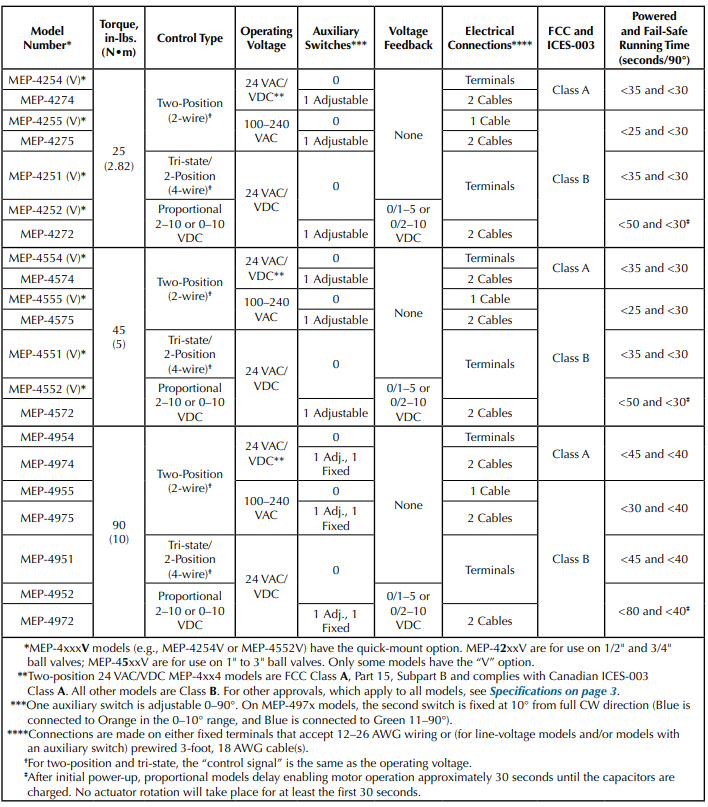
MEP-4xx1 tri-state/two-position (four-wire) models are designed for use with floating thermostats or controllers. MEP-4xx4/4xx5 two-position (two-wire) models are available in 24 VAC/VDC or 100–240 VAC models. MEP-4x7x models also have one fully adjustable, built-in SPDT auxiliary switch for remote position indication or equipment interface. MEP-497x models include a second fixed switch at 10° from full CW direction. A three-foot cable is included with the switch(es).
All actuators mount directly to 1/4- to 5/8-inch (6 to 16 mm) round shafts or 1/4- to 7/16-inch (6 to 11 mm) square shafts, eliminating the need for expensive and complicated linkages. A non-rotation bracket, to prevent lateral movement, is included with each actuator. A gear disengagement button allows easy manual positioning of the actuator.
Features
- Efficient, durable, capacitor-driven fail-safe option with switch-selectable direction provides consistent torque in both powered and fail-safe modes
- The fail-safe option, on proportional and tri-state models, can be turned off temporarily for testing purposes or permanently if desired
- Proportional models include “anti-jitter” circuitry, optional auto-mapping of the full input signal range over a reduced actuator stroke, and switchselectable 0/1–5 or 0/2–10 VDC feedback
- MEP-4x7x models have one fully adjustable, built-in SPDT auxiliary switches, and MEP-497x models include a second fixed switch at 10° from full CW direction
- Connections are made with prewired 3-foot, 18 AWG cable(s) or fixed terminals that accept 12–26 AWG wiring (see Models on page 2)
- Direct mounting to standard shaft sizes, gear disengagement button, and adjustable mechanical end stop
- Patented valve body quick-mount option on MEP-4xxxV models
NOTE: For similar actuators without fail-safe, see the MEP-4000/4800 Series and the MEP4201/4501/4901 data sheets.
NOTE: See also (Quick-Mounting) “V” Models Valve Cross-Reference.
NOTE: The above chart lists the differences among models. Supply power, supply frequency, transformer sizing, fail-safe, angular rotation, noise level, mounting, dimensions, weight, enclosure material, position indication, servicing, quality standard, warranty, and environmental limits are the same for all models.
Specifications:
| Control Signal | |
| Proportional | 0 to 10 VDC or 2 to 10 VDC, switch selectable |
| Tri-state/2-Pos. | See Supply Voltage |
| Two-position | See Supply Voltage |
| Supply Voltage | |
| Low Voltage | 24 VDC/VAC (+20%/–15%), Class 2 only (MEP-4xx1/ 4xx2/4xx4) |
| Line Voltage | 100–240 VAC (MEP-4xx5) |
| Supply Frequency | 50/60 Hz for VAC operation |
| Supply Power | 6 VA normal operation, 19 VA peak initializing |
| Transformer Sizing | g 20 VA |
| Initialization Time | 30 seconds (on power-up) for proportional models only |
| Feedback Output | 0/1 to 5 VDC or 0/2 to 10 VDC (switch selectable, proportional models only) |
| Auxiliary Switches | |
| Rating | SPDT 6 A resistive load (3 A motor load) @ 250 VAC |
| MEP-427x/457x | 1 switch, adjustable 0 to 90° |
| MEP-497x | 2 switches; 1 adjustable 0 to 90° and 1 fixed at 10° from full CW direction |
| Fail-Safe Control | Switch selectable, CW/OFF/ CCW on proportional and tri-state models, CW/CCW on 2-position models |
| Fail-Safe Type | (Electronic) capacitor driven |
| Angular Rotation | 0 to 95°, fully adjustable with mechanical stop |
| Torque | |
| MEP-42xx | 25 in-lbs. (2.82 N•m) |
| MEP-45xx | 45 in-lbs. (5 N•m) |
| MEP-49xx | 90 in-lbs. (10 N•m) |
| Noise Level | < 45 dBA max. at 1 meter |
| Mounting | Direct to 1/4 to 5/8 inches (6 to 16 mm) round or 1/4 to 7/16 inches (6 to 11 mm) square shaft by adjustable “V” bolt and supplied non-rotation bracket; minimum recommended damper shaft length is 1-5/8 inches |
| Brackets | Non-rotation bracket HMO4001 (supplied with MEP-4x7x and all MEP-49xx models) or HMO-4002 (supplied with MEP-425x and MEP-455x); HPO-5073 or HPO-5074 required for mounting to valves |
| Connections |
| Power/Signal | Fixed wire clamp type terminal block, 12–26 AWG, copper, or prewired 3-foot, 18 AWG cable |
| Aux. Switch(es) | 3-foot 18 AWG cable |
| Dimensions | 6.000 x 2.812 x 3.406 inches (152.4 x 71.4 x 86.5 mm) |
| Weight | 1.5 lb. (0.68 kg) |
| Enclosure | Flame retardant polymer, NEMA 2 and IP54—to guarantee IP54, install an HMO4521 liquid-tight cord grip (all models) or an HPO-4051 assembled wiring kit (MEP4x51/4x52/4x54 models only) |
| Position Indication | Visual indicator, 0° to 95° |
| Servicing | Maintenance free |
| Quality Standard | ISO 9001 |
| Warranty | 5 years (from mfg. date code) |
| Environmental Limits | |
| Operating | –22 to 131° F (–30 to 55° C) |
| Shipping | –40 to 176° F (–40 to 80° C) |
| Humidity | 5 to 95% RH (non-condensing) |
Recent Posts
-
WERA Advent calendar 2025, 28 pieces
The 2025 Wera Advent calendar includes a comprehensive screwdriving workshop for the most common sc …2025 Nov 19th -

Wera Bicycle tool set
Bike tool set with ratchet, bits, sockets and a bitholding screwdriver in the very compact Tool-Che …2025 Jul 24th -
DUCT CARBON DIOXIDE TRANSMITTER
The duct CO2transmitter uses a highly accurate andreliable non-dispersive infrared (NDIR) sens …2025 Apr 3rd