WI-FI ENABLED BOILER CONTROL CPU-0600 BY HBX
CPU-0600 INTRODUCTION
The CPU-0600 is designed to be a stand-alone Outdoor Reset Control device. The purpose and function of the CPU-0600 is to provide control for multiple applications. The applications are selectable through a full touch screen display on the programming interface and consist of Boiler, Mixing, Differential Setpoint, Dual Setpoint and Pump Sequencer. The CPU-0600 is a Wi-Fi enabled control that allows access through the HBX Sensorlinx mobile app.
Boiler Control
The use of the CPU-0600 as a Boiler Control allows the capability to run up to four (4) On/Off boilers, and three (3) modulating boilers with DHW requirements. Expandability for more stages is possible with additional CPU-0600 controllers.
Mixing Control
As a Mixing Control, the CPU-0600 has the capability to run four (4) On/Off Boilers and three (3) modulating boiler. Mixing types include Modulating Mixing, Floating Action Valve and Injection Pump
Pump Sequencer
This control allows the system to sequence and cycle pumps, override pumps and turn the pump off when the outdoor temperature goes above a certain value (WWSD).
Differential Setpoint Control
The CPU-0600, when selected the control will allow to run a temperature differential for a setpoint.
Dual Setpoint
This mode is for use when one or two independent setpoints are needed in a system.
FEATURES
• Remote access for Apple® and AndroidTM devices via Sensorlinx mobile app
• Full-Colour touch screen display
• Control up to 4 on/off boiler stages per controller
• Control up to 3 modulating boilers (0-10 VDC) per controller
• Expandable up to 16 on/off boiler stages and/or 12 Modulating boilers.
• DHW control
• Boiler lead lag and rotation on time or cycles
• Boiler and DHW differential
• Multiple pump control options (system, boiler, DHW)
• Multiple mixing control options (Injection, Mod, Floating)
• Outdoor temperature reset with WWSD
TECHNICAL DATA AND DIMENSIONS
CPU-0600 TECHNICAL DATA
Specifications:
4 x thermistor Input (10k Ohm)
2 x Demand output relays 24VAC 2A
4 x Relay Outputs 240VAC 5A (Dry Contacts)
1x Input 120VAC +/- 10% 50/60Hz 15A Max
3 x Pump Relay 240VAC 5A
Combined relay power should not exceed 15A
Weight: 0.408Kg
Dimensions: 131mm W x 246mm H x 66.71mm 5.16in W x 9.83in H x 2.64in
ETL Listings:
Meets CSA C22.2 No. 24 Meets UL Standard 873
ETL Control No. 3068143
Storage:
50°F to 104°F (10ºC to 40ºC)
CPU-0600
WiFi: 2.4GHz Network Only
FCC ID: 2AHMRESP125
Torque: 0.3687811ft-lb
CPU-0600 INSTALLATION
The CPU-0600 is designed to be wall mounted or installed in a separate electrical enclosure. The unit should be installed inside and protected from falling water and high humidity conditions. With all the covers in place, it is designed to protect any individual from accidental electrical shock. It is not suitable for installation in hazardous locations and should not be close to any electromagnetic fields.
• Identify the four mounting holes on the CPU-0600, mark on the wall the desired location of mounting • Pre-drill, anchor and fasten four screws for mounting
• Hang CPU-0600 and fasten tight to desired locations
• Complete wiring connections in accordance with terminal locations
CONTROL MODE
The programming instructions for the CPU-0600 are broken down into the five control modes listed below. When the control is first plugged in you are asked to select which control mode you would like your CPU-0600 to operate in.
STAGING MODE (DEFAULT) – Programming for this mode can be found on pages 6 through 14. This mode is used when running boilers only. The boiler configurations available in this mode are three (3) modulating, On/Off boiler, two (2) stage On/ Off boiler, three (3) stage On/Off boiler and four (4) On/Off boiler. Staging expandability is possible with additional CPU-0600 controllers. In this mode the control is able to control DHW and operate a boiler, system, and DHW pump(s).
MIXING MODE – Programming for this mode can be found on pages 15 through 24. This mode is used when running mixing pumps or valves. Mixing configurations include PMIp, Modulating, and Floating Action Valve. In this mode the control can run up to four (4) on/ off boilers or three (3) mod boiler(s).
DIFFERENTIAL SETPOINT MODE – Programming for this mode can be found on pages 25 through 28. This mode is used when running a differential setpoint. In differential mode, the control will also send a modulating signal output based on how far the control is from the differential. This can be used to run a pump in modulating applications for constant flow.
DUAL SETPOINT MODE – Programming for this mode can be found on pages 29 through 31. This mode is used when one or two independent setpoints are needed. Each setpoint is set up individually and each has its own thermistor input and relay outputs: Each setpoint has its own normally open and normally closed contacts (which can be used for heating and/or cooling).
PUMP SEQUENCER MODE – Programming for this mode can be found on pages 32 through 34. This mode is used to provide pump control for two pumps in a duty, standby situation. This control allows the system to sequence and cycle pumps, override pumps and turn the pumps off when the outdoor temperature goes above a certain value (WWSD)
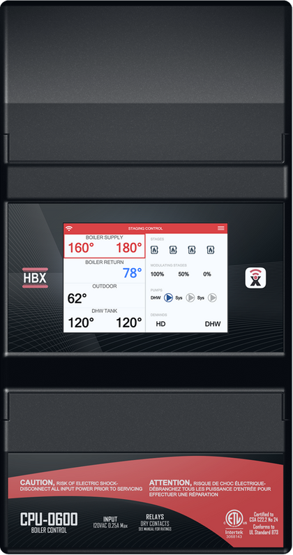
STAGING MODE: MAIN SCREEN
WI-FI – Indicates that the control is connected to a 2.4 GHz Wi-Fi network.
BOILER SUPPLY – Indicates the boiler supply temperature and target. If there is a demand for heating the box will be bordered with a red outline, and the staging output(s) in the lower wiring chamber will be closed.
BOILER RETURN – Indicates the boiler return temperature.
OUTDOOR – The outdoor temperature will be displayed. This option will also display if the control is in WWSD (Warm Weather Shutdown).
DHW TANK – It will display the DHW temperature and target. If there is a demand for DHW the zone will be bordered with a red outline.
STAGES – Indicates how many boilers are being utilized in your system setup. When a boiler is activated by a heat demand the boiler will light up in respect to their classification.
MODULATING STAGES – Indicates how many modulating boilers are being utilized in your system setup. When a modulating boiler is activated by a heat demand the modulating boiler percentage will start at the minimum mod percentage (%). When there is no demand (off) the modulating percentage (%) will displayed as 0%.
PUMPS – When a pump is activated by a call you will see pump (P1) ,(P2), (P3) light up in respect to their classification, their associated contacts PUMP 1, PUMP 2, PUMP 3 can be found in the lower wiring chamber will be closed.
DEMANDS – When the delegated demand is active it will light up (DEMAND 1 - HD) or (DEMAND 2 – DHW/SETPOINT) thus in turn the associated demand in the upper wiring chamber will be closed.
STAGING MODE: STAGE SEQUENCE SETUP
The CPU-0600 allows for expandability for more boiler staging between controllers. A maximum of four (4) controllers can be utilized for a maximum of 16 boiler stages. When using more than one CPU-0600, to allow them to communicate wirelessly between each other, they will need to follow a sequential order.
STAGE SEQUENCE SETUP
– This setting will allow you to select the stage sequence in your systems setup. The first sequence is labelled Primary and represents sequence 1-4.
• Primary (Stages 1-4)
• Secondary (Stages 5-8) *CPU-0600 #2
• Secondary (Stages 9-12) *CPU-0600 #3
• Secondary (Stage 13-16) *CPU-0600 #4
CONTROL ID – If the Sequence was set to the Primary then the number under Control ID will represent this CPU-0600’s ID. If the CPU Sequence was set to any sequence other than Primary, that CPU-0600’s Control ID can be set to match the value of the Primary CPU0600 Control ID and the CPU-0600’s will then LINK automatically. The CPU-0600’s will be LINKED when the Sequence Link symbol appears on the top left of the Main Screen for both controllers.
STAGING MODE: CONTROL STATUS
Sync Code: Sync code of the CPU-0600.
• Wi-Fi Network : displays current SSID network connected to
• Wi-Fi Password: displays network password connected to
• Wi-Fi Strength – displays Signal strength of the network connected to
STAGING MODE: DESIGN TEMPERATURES
OUTDOOR RESET – This is used in the outdoor reset design calculation. This option should be set to reflect your specific city or region. (OFF/-40°F to 127°F)
BOILER SETPOINT – When a heat demand is present and the control is not in WWSD, the control will target this temperature for heating. (OFF/2°F to 210°F)
MAX BOILER TEMP – This is used in the outdoor reset design calculation, and also serves as the maximum setting for the boiler. This is the maximum boiler temperature for the coldest day. (OFF/2°F to 210°F)
MIN BOILER TEMP: This is the minimum boiler temperature. Set this to the temperature you would like the boiler to be when the outdoor temperature approaches WWSD. (OFF/2°F to 210°F)
USE WEB OUTDOOR TEMP: This setting can be used for outdoor temperature reading via the web instead of installing an outdoor sensor. The control must be connected to a Wi-Fi network and the user must set the controller to a building via the Sensorlinx mobile app for this setting to work. (ON/OFF)
WARM WEATHER SHUTDOWN (WWSD): This setting is used to set the temperature in which the CPU-0600 will go into WWSD. If the system rises above this temperature, the system will be shut off. In WWSD the boilers and all pumps will shut off. (35°F to 120°F) Default: 70°F
WWSD TIME: This setting is used as a lag time for WWSD. This will hold the control from entering WWSD until this time has elapsed. The timer starts when the outdoor temperature hits WWSD. This setting is useful in the shoulder seasons when there are large outdoor temperature swings.
(0°F to 240°F) Default 0°F
ROTATE CYCLES: Set the number of cycles at which you would like to rotate the boilers. One cycle is described as the boiler going on and then off. (OFF/1 to 240)
NUMBER OF MOD STAGES – This setting will allow you to select the number of modulating stages.
MODULATING TIME – This setting sets the time between the steps when the boiler needs to increase or decrease the firing rate. Each step is 1% for all situations. (1S to 240S)
MIN MOD PERCENT – This setting is used to set the lowest modulating level the boiler can go down to. This will also be the starting point whenever there is a new demand. (1% to 99%)
MOD OUT SETPOINT – In this mode the 0-10VDC signal does not directly run the burner. The 0-10VDC signal is interpreted by the boiler as a setpoint. The boiler in this mode will modulate the burner to achieve that setpoint. ex: 4VDC is equal to 140°F
(ON/OFF)
Recent Posts
-
WERA Advent calendar 2025, 28 pieces
The 2025 Wera Advent calendar includes a comprehensive screwdriving workshop for the most common sc …2025 Nov 19th -
Wera Bicycle tool set
Bike tool set with ratchet, bits, sockets and a bitholding screwdriver in the very compact Tool-Che …2025 Jul 24th -
DUCT CARBON DIOXIDE TRANSMITTER
The duct CO2transmitter uses a highly accurate andreliable non-dispersive infrared (NDIR) sens …2025 Apr 3rd


