Sizing/Selecting – Water Valve Application

Pressure Dependent Valves
- 1)What type of valve would the customer like?
Ball Valve (CCV, ZoneTight, Industrial), Globe Valve or Butterfly Valve
- 2)Calculating the CV.
What is CV?
- CV = The amount of water flow (GPM) through a fully open valve with 1 psi pressure drop.
Why is CV important?
If CV is too high, that means the valve is oversized and this will result in sloppy control and inefficient system performance.
If CV is too low, that could result in insufficient flow and starve the coil. You may never get the required power output out of the coil.
How do we calculate CV?
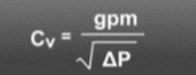
GPM = Gallons Per Minute (flowrate) going through the valve.
Delta P = Pressure Drop though the valve. We want to design Delta P to match the pressure drop across the coil which typically between 3-5 psi. If the pressure drop is unknown, we use the rule of thumb 4 psi. This creates an easy calculation. The square root of 4 is 2, which means we are dividing the GPM by 2.
- Ex.

- 3)What is the Line Size?
This is the system’s pipe size. It is recommended that we don’t size the valve less than 2 sizes smaller than the Line Size. We can go down to half the Line Size if needed, but it is not recommended.
- 4)Selecting the Valve Size.
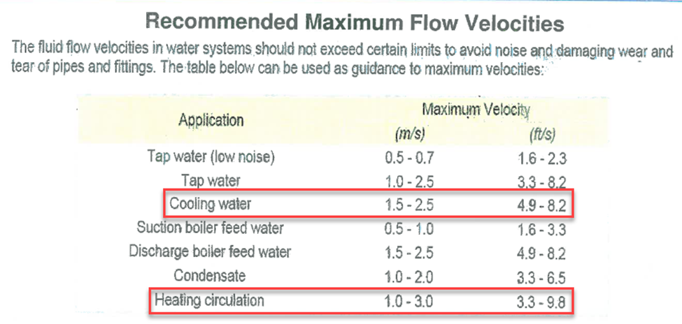
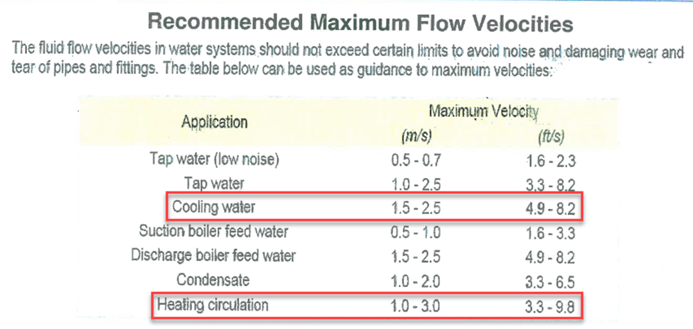
We need to size the valve based on the velocity. Too high of velocity can cause noise problems or cavitation in the valve. We have recommended velocities depending if it’s a heating or cooling system. Heating is between 3.3 – 9.8 ft/sec and cooling is between 4.9 – 8.2 ft/sec.
Where do we check this?
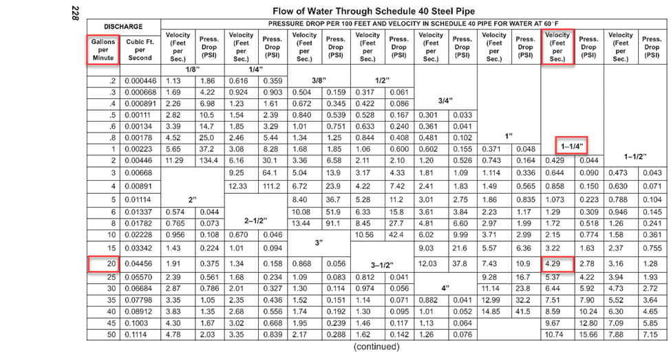
In the Fisher Water Table. Sticking with our same example, 40 GPM. We can go with either 1 ¼ inch or 1 ½ inch valve, depending what the application is for? Heating or cooling. Heating we can go as low as 1 ¼ inch, but in cooling we shouldn’t go lower than 1 ½ inch. The velocity on the 1 ¼ inch is above the 8.2 ft/sec recommended maximum velocity.
Or online calculator: Click here

We need to compare this information with the Line Size. It is not recommended to go down more than two sizes. Ex. If Line Size is 2 inch, we shouldn’t go smaller than 1 ¼ inch on the valve.
If we are selecting a Valve for an on/off application, we can select the Line Size as we are not worried about the control of flow.
- 5)Do we need 2 way or 3 way?
What type of valve is required?
2 way valve is a 2 port valve, one inlet and one outlet.
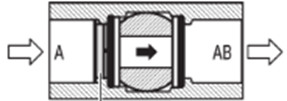
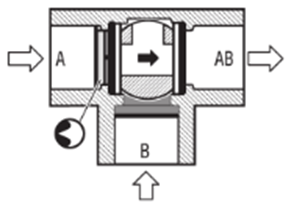
3 way valve is a 3 port valve. It can be either mixing or diverting.
Mixing = 2 inlets and 1 outlet
Diverting = 1 inlet and 2 outlets
Mixing
Diverting

- 6)Select the Valve.
We now know what type of valve we need, the valve size and the required CV. Now we need to select the appropriate valve. Let’s continue to use our example of 40 GPM with a CV rating of 20. The application is cooling so we are going to go with a 1 ½ inch valve. Customer wants to go with a CCV. It is a 2 way valve.
What valve do we select? (Go to our Product Guide)

We have two options. We can either go with the B238 which has a CV of 19 or the B239 which has a CV of 29. What one do we choose?
We want to select the valve that will provide us the closest actual pressure drop to our design pressure drop of 4. We can back calculate it to see what our actual pressure drop is. The above valves have fixed CVs, so we can plug in our fixed CV to the formula to calculate the actual pressure drop.


We want to select the valve that is closet to our design pressure drop which was 4. In this case the valve with the 19 CV is the best selection. It’s actual pressure drop is 4.4 psi compared to our design of 4 psi. The CV 29 is not the best choice as it’s actual pressure drop is 1.90 psi.
- 7)Selecting the actuator. Is Fail Safe or Non-Fail Safe required?
With Fail Safe, when there is a loss in main power the actuator fails to a specific position. (Spring Return is open or closed & Electronic Fail Safe can fail anywhere between 0 degrees and 90 degrees. This is adjusted with a dial on the face of the actuator).
With Non-Fail, when there is a loss in main power the actuator stops in its last position.
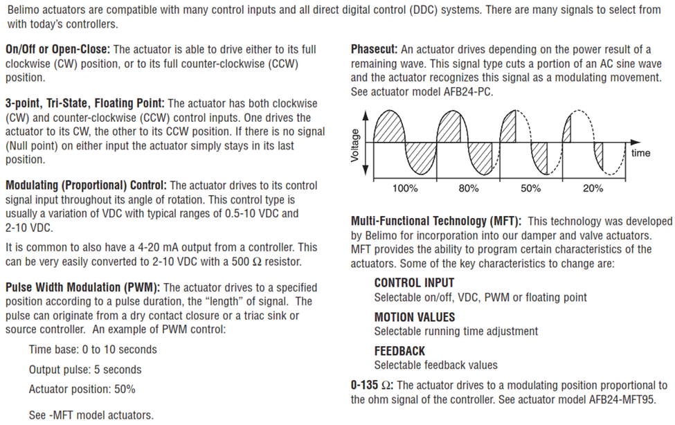
- 8)How is the actuator being controlled?
- 9)Are any accessories required, Auxiliary Switches or Enclosures?
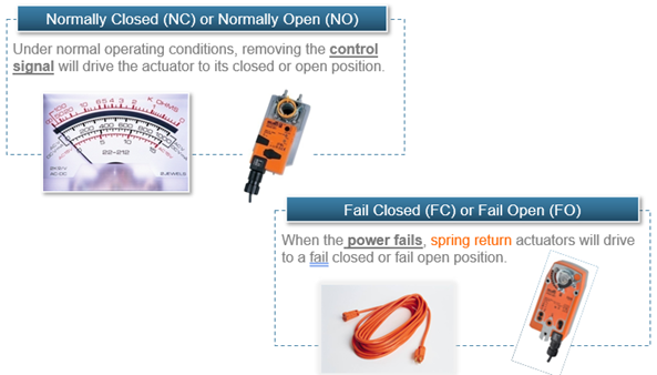
- 10)Setting the configuration. We need to select the Normal Position and the Fail Position for the valve assembly.
Normal Position is the starting position of the actuator. (Ex. The position at 2 VDC). If control signal is lost, the actuator will drive to its Normal Position.
Fail Position is what happens when the actuator losses main power, it is failing open or closed. It can also be anywhere between 0 – 90 degrees if it is an Electronic Fail Safe actuator. This can be adjusted with the dial on the face of the actuator or in the Belimo Assistant App, depending on the actuator.
Pressure Independent Valves
- 1)What type of valve would the customer like?
PIQCV, ePIV or Energy Valve
- 2)What is the required flow rate?
What is the flowrate in GPM? If the customer provides us the flow rate in Litres Per Second (L/S) convert it to Gallons Per Minute. The formula is L/S x 15.85.
- 3)Choose a valve model number with the closest V’Max rating to the required flowrate (round up). No equations are required.
Ex. If the customer needs an ePIV valve with 20 GPM, we would select the P2125SU-285.
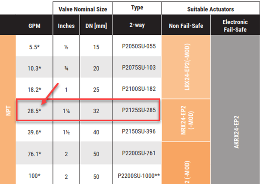
We still have to take the Line Size and Velocity into consideration. It is still recommended to not size the valve 2 sizes below Line Size. We can go down to half the Line Size if needed, but it is not recommended. In addition, we need to double check the velocity in the Fisher Water Table to make sure we don’t have too much velocity through the valve.
- 4)What type of actuator is required?
- Fail Safe or Non-Fail Safe?
With Fail Safe, when there is a loss in main power the actuator fails to a specific position.
With Non-Fail, when there is a loss in main power the actuator stops in its last position.
The Energy Valve and ePIV’s are all modulating type actuators. On the ePIV, you have the option of getting a MODbus or BACnet actuator on the Non-Fail Safe actuators. They have the – MOD at the end. The Energy Valves come standard with MODbus and BACnet compatibility.
The PIQCV’s have on/off, floating point or modulating controls. Modulating can be 2-10 VDC or 0-10 VDC. The (– SR) CQKB or CQB actuators can be programmed for 0-10 VDC.
We have to select the configuration on the PIQCV actuators. These can not be changed in the field, so it is important to select the right configuration. The configurations are as follows:
Non-Fail Safe (CQB)
L = Normally Open
R = Normally Closed
Fail Safe (CQKB)
-LL = Normally Open/Fail Open
-RR = Normally Closed/Fail Closed
-LR = Normally Open/Fail Closed
-RL = Normally Closed/Fail Open
The First letter represents the Normal Position, and the second letter represents the Fail Position.
Recent Posts
-
WERA Advent calendar 2025, 28 pieces
The 2025 Wera Advent calendar includes a comprehensive screwdriving workshop for the most common sc …2025 Nov 19th -
Wera Bicycle tool set
Bike tool set with ratchet, bits, sockets and a bitholding screwdriver in the very compact Tool-Che …2025 Jul 24th -
DUCT CARBON DIOXIDE TRANSMITTER
The duct CO2transmitter uses a highly accurate andreliable non-dispersive infrared (NDIR) sens …2025 Apr 3rd

